INTRODUCTION TO PLANKING - PART ONE
Making a Start
The following "advice" is based upon the construction of the John Lewis designed Petrel.
The first task is the construction of a building board. It is essential that this is constructed carefully and reasonably robustly, to avoid any distortion in construction and thereby ruin all your hard work. For a building board the author uses a perfectly straight length of 4 x 2in (10 x 5cm) screwed to a 1.5 x 1.5in (4 x 4cm) length on its underside, making a rigid non distorting T section, which has seen him through many hulls. Though for a one off hull, a 6in (15cm) wide piece of chipboard, the type sold in DIY stores for shelving can be used. Screw a length of 2 x 1in (5 x 2.5cm) softwood placed vertically down the length of the board on both edges to resist any tendency to warp and provide the necessary stiffness. You will remember to make your board longer than the L.O.A. won't you? A couple of inches (50mm metric equivilant) will do the trick. Next mark the section spacings on the top surface of the base board using a metal edged square and a Stanley knife or similar. Run a pencil along the resultant groove to emphasise the station line for easier visibility when setting up the sections. Finally mark a centre line down the length of the building board. A marking gauge is ideal for this task if you have one.
It is now necessary to transfer all the hull sections on to 5 or 6mm plywood, which must be accurately carried out for any boat if the finished model is to do justice to the designer's original concept, but especially so in the case of the 6m class where girth measurements etc. are an integral part of the measurement and rating process. The method the author now uses, although perceived by some as somewhat tedious, if carried out with reasonable care will virtually guarantee the lines are accurately transferred into a building jig.
Transferring the Lines
Ensure the drawing is laid flat, especially in the area of the full-size body sections. Incidentally, if requested when ordering your plans, all suppliers will ensure that no fold lines appear on the body sections, which is a great help at this stage.
First of all extend each section from the water line to a common building datum line, which must be parallel to the water line. Mark this on the drawing. The author finds a line approximately one inch above the sheer line at the bow section is about right. This will obviously vary dependant upon the sheer to the bow. It is interesting to note here that whereas the L.W.L. is probably the most important datum line to the designer ( and dare the author say it, the measurer! ), the builder will be far more interested in the accuracy of the building datum line in relation to the L.W.L. Because this is his main reference point.
Lay a sheet of tracing paper over the body sections including the extended area to the building datum, and fix the paper with a couple of small pieces of masking tape to ensure there can be no movement whilst transferring the lines. Now trace all of the left hand / stern body sections using a sharp pencil, but do not make any allowance for hull planking at this stage. As well as the section outline and centre line, the author also transfers the position of the L.W.L and deck line, for a reason that will become apparent later. Remove the tracing paper and fold carefully down the marked centre Iine; now trace through the outlined half-body section, so upon opening out the paper you are presented with exact full size sections for one half of the boat, ie: the stern sections. It is now necessary to repeat the process for the right hand/bow sections on a fresh piece of tracing paper.
The next stage is to transfer each individual body section onto a piece of thin card using a sharp pencil and carbon paper. Having done this cut out each section so you end up with a full size template for each hull section.
Now open up a pair of compasses to the required finished planking width, which in the authors case is 3.5mm, and using the edge of the card template as a guide for the compass point, run the compass round the body sections from sheer to sheer, so ensuring a very accurate reduction for the hull planking. Finally cut the small 3.5mm strip away to give you the finished template.
This might appear to be a lot of work to produce a set of accurate hull templates but it can in fact be completed in just two pleasant evenings without difficulty. At this stage the author also makes full size templates for the rudder, fin and bow profile, which helps building progress more rapidly later on. A usefull tip at this stage is to line up the templates, bow to mid section, and stern to mid section, with the lines facing you. If anything is not fair you will quickly observe it, thus saving expensive mistakes
Now transfer the body sections onto 5mm or 6mm plywood; scrap can be obtained quite cheaply from most DIY or timber merchants. But please be aware of distortion, and its possible consequences on bulding accuracy.
When drawing out the hull sections also mark onto the plywood the L.W.L, centre-line, and deck line, plus the slot required for the keel/backbone assembly. Give some thought to the deck edge. Will you be dropping the deck into the hull onto the inwhale inside the shearline plank?. In which case make allowance for the thickness of the decking material when marking out for the inwhale. And, of course, your planks must be laid from the deck sheerline. If not, and the deck is being mounted onto the plank edge, an allowance will again need to be made for its thickness. The authors own preference is the let the inwhale into the plywood body sections making allowance for the thickness of the decking material to sit on it, then glue the sheer plank to it. This makes for a cleaner finish to fitting the deck. Be aware however, that the inwhale will need to be tapered at the bow and stern. Leave a small shoulder on the shadow of 2 or 3 plank widths at the deck line for the shearline plank to rest on. ( Please note, that the shoulders in the picture have been left deliberately wide for ease of display in the picture ). The backbone is generally laminated from three lengths of planking, however towards the aft water-line ending additional laminations are required to accommodate the skeg/bustle arrangement. Note detail on photograph of building jig.
Building Jig
The Backbone
Cut out the plywood sections ( called shadows ); using a fret-saw if you have one or if not a coping saw will suffice. If you cut just outside the marked line you can run a file or glasspaper over the edge to ensure a perfect finish results. Do not however go below the line. Remember what has already stated about skin girth measurements etc. Repeat the section lining up test as previously done with the cardboard templates.
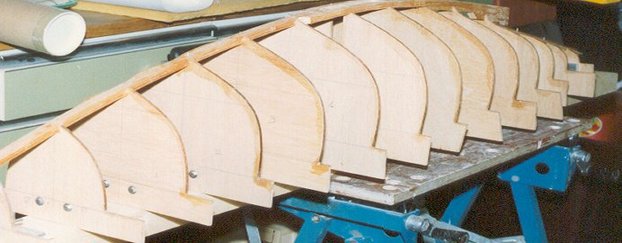
Screw softwood battens approximately 1in ( 25cm ) square to the lower edge ( building datum ), on the unmarked face of each shadow. Next mount the shadows to the previously constructed building board by screwing from underneath through pre-drilled and countersunk holes in the building board into the battens attached to the hull shadows. A this point it is worth emphasising securing the shadows from underneath. It you do not do this, it will be exceptionally difficult to gain access to the screws once the hull is built, when you wish to remove it from the building board. Ensure that the centre-line drawn on each shadow lines up accurately with the centre-line drawn on the building board, ( this was why the batten was screwed onto the other face ). The use of a square will also help in checking the vertical alignment of each shadow. A good prctice is to devise an arrangement by which the spacing of the shaddows can be maintained higher up from the building board. Away from the secured bottom a shaddow can sometimes lean. The result is an inaccurate hull. The author finds that standing back a couple of paces and looking down the length of the assembly will usually show if centre-lines are mis- aligned, especially from one shadow to another.
All the forward shadows must be placed facing towards the bow and the aft shadows facing the stern, see photo, as this will remove the requirement for any bevelling. To stop the planking from sticking to the shadows run a candle over the edges or cover them with Sellotape. Having completed the jig you are now ready to commence hull construction. First laminate the backbone using three planks; the use of the template showing the bow profile assists in ensuring the correct curve is maintained. At this stage it may suit to create the bow profile by cutting it from a solid piece of lightweight wood.
Cut out the plywood sections ( called shadows ); using a fret-saw if you have one or if not a coping saw will suffice. If you cut just outside the marked line you can run a file or glasspaper over the edge to ensure a perfect finish results. Do not however go below the line. Remember what has already stated about skin girth measurements etc. Repeat the section lining up test as previously done with the cardboard templates.
Screw softwood battens approximately 1in ( 25cm ) square to the lower edge ( building datum ), on the unmarked face of each shadow. Next mount the shadows to the previously constructed building board by screwing from underneath through pre-drilled and countersunk holes in the building board into the battens attached to the hull shadows. A this point it is worth emphasising securing the shadows from underneath. It you do not do this, it will be exceptionally difficult to gain access to the screws once the hull is built, when you wish to remove it from the building board. Ensure that the centre-line drawn on each shadow lines up accurately with the centre-line drawn on the building board, ( this was why the batten was screwed onto the other face ). The use of a square will also help in checking the vertical alignment of each shadow. A good prctice is to devise an arrangement by which the spacing of the shaddows can be maintained higher up from the building board. Away from the secured bottom a shaddow can sometimes lean. The result is an inaccurate hull. The author finds that standing back a couple of paces and looking down the length of the assembly will usually show if centre-lines are mis- aligned, especially from one shadow to another.
All the forward shadows must be placed facing towards the bow and the aft shadows facing the stern, see photo, as this will remove the requirement for any bevelling. To stop the planking from sticking to the shadows run a candle over the edges or cover them with Sellotape. Having completed the jig you are now ready to commence hull construction. First laminate the backbone using three planks; the use of the template showing the bow profile assists in ensuring the correct curve is maintained. At this stage it may suit to create the bow profile by cutting it from a solid piece of lightweight wood.
Make sure that you allow for a capping piece to be laminated to the bow plank endings, ensuring the final L.O.A. is exactly 57 inches as specified. A decision by the builder is required at this point, as to how best accomodate the Class Rule 3.3.11. The forward 13 mm of the hull shall be made of elastomeric material. The options are.
A. To continue the planking to the true shape of the bow, then bond onto it the Rule requirement, thus increasing the L.O.A.
B. To end the planking of the bow flat and square, then bond onto it a shaped piece to the Rule requirement, thus retaining the correct L.O.A.
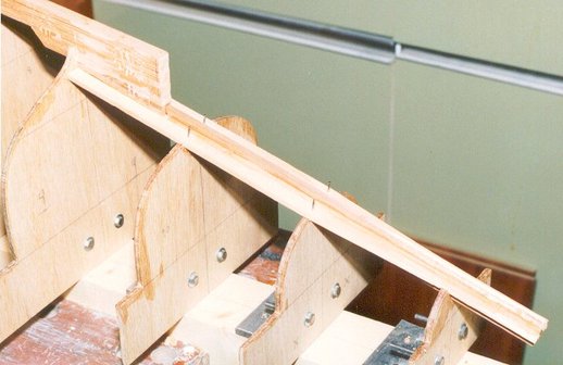
The backbone will require additional planks either side of the fin root location, extending slightly longer, approximately two inches each end. The top most square edges of the three laminated backbone planks will at this stage, have to be shaped to the profile of the shadow, to allow the planks to lay flat. Laying a plank along the shadows and onto the backbone will show where and how much needs to done.
Hopefully by now you will have laid in your stock of hull planking. A good local sawmill will usually oblige with the cutting if you purchase the timber from them. The authors preference is to purchase the very best quality western red cedar wood that he can find. Light weight, quality grain and colour are the goals. This is then stocked untill its needed, and then cross sawn, and finally cut into planks of the dimensions required. A hand held circular saw, with suitable blade mounted on the underside of a good flat work surface. With the fences secured with G clamps and taking all sensible precations over fingers and eyes, is the method used by the author.
The planking the author uses is 4mm thick by 15mm wide as a standard base for shaping ( this gives a good shearplank, and topside to mid section ), so allowing 0.5mm for sanding, he arrives at 3.5mm for the finished planking thickness. Having now planked more hulls that he cares to recall. The author believes the ideal commencing planking dimensions for a 6 Metre to be 4mm thick x 12mm wide. The slight extra thickness appears to reduce any tendency of distortion between the shadows, helping to produce a good glue line, whilst the extra width requires marginally fewer planks but is still narrow enough to deal with the curves encountered on most boats of this class. A word of caution though. If you use planks too wide, great difficulties will be experienced in laying the planks flat onto the sections.
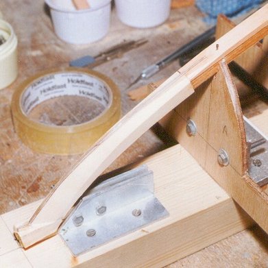
The main backbone will be cut away eventually to take the fin. The stern overhang part of the backbone, see photo B, is in fact a separate piece joined to the main backbone by several laminations of planking material. This rear backbone section will require an additional plank either side let into the upright sections to effectively treble the width of the backbone. This enables the plank ends to have an adequate glue surface in this important area. Onto this aft backbone section glue a piece of planking down the centre-line, end on and reduced to 6mm, to which the tapered plank ends will eventually butt, see photo B. This is good practice as it helps the builder avoid any hollows in a vital area of measurement.
A. To continue the planking to the true shape of the bow, then bond onto it the Rule requirement, thus increasing the L.O.A.
B. To end the planking of the bow flat and square, then bond onto it a shaped piece to the Rule requirement, thus retaining the correct L.O.A.
The backbone will require additional planks either side of the fin root location, extending slightly longer, approximately two inches each end. The top most square edges of the three laminated backbone planks will at this stage, have to be shaped to the profile of the shadow, to allow the planks to lay flat. Laying a plank along the shadows and onto the backbone will show where and how much needs to done.
Hopefully by now you will have laid in your stock of hull planking. A good local sawmill will usually oblige with the cutting if you purchase the timber from them. The authors preference is to purchase the very best quality western red cedar wood that he can find. Light weight, quality grain and colour are the goals. This is then stocked untill its needed, and then cross sawn, and finally cut into planks of the dimensions required. A hand held circular saw, with suitable blade mounted on the underside of a good flat work surface. With the fences secured with G clamps and taking all sensible precations over fingers and eyes, is the method used by the author.
The planking the author uses is 4mm thick by 15mm wide as a standard base for shaping ( this gives a good shearplank, and topside to mid section ), so allowing 0.5mm for sanding, he arrives at 3.5mm for the finished planking thickness. Having now planked more hulls that he cares to recall. The author believes the ideal commencing planking dimensions for a 6 Metre to be 4mm thick x 12mm wide. The slight extra thickness appears to reduce any tendency of distortion between the shadows, helping to produce a good glue line, whilst the extra width requires marginally fewer planks but is still narrow enough to deal with the curves encountered on most boats of this class. A word of caution though. If you use planks too wide, great difficulties will be experienced in laying the planks flat onto the sections.
The main backbone will be cut away eventually to take the fin. The stern overhang part of the backbone, see photo B, is in fact a separate piece joined to the main backbone by several laminations of planking material. This rear backbone section will require an additional plank either side let into the upright sections to effectively treble the width of the backbone. This enables the plank ends to have an adequate glue surface in this important area. Onto this aft backbone section glue a piece of planking down the centre-line, end on and reduced to 6mm, to which the tapered plank ends will eventually butt, see photo B. This is good practice as it helps the builder avoid any hollows in a vital area of measurement.
